Why Wire Diameter Changes What a Clip Can Hold
A cable clip grips whatever the outside of the cable measures, not the number printed on the drum, and those two figures differ: KUKA CABLE publishes an overall diameter of 5.5 mm for its 4 mm² solar wire, 6.0 mm at 6 mm² and 7.5 mm at 10 mm². The same table gives nominal weights of 59 g/m, 78 g/m and 130 g/m, so a clip sized for one cross-section is asked to carry a different mass and to close on a different circumference.
Key takeaways
- Published diameters are 5.5 mm at 4 mm², 6.0 mm at 6 mm² and 7.5 mm at 10 mm², so nominal cross-section is not a clip size.
- Published weights rise from 59 g/m to 130 g/m across those three sizes, which is the load a clip set has to carry.
- A minimum bending radius of 4 × outer diameter is published for the family, so the routing curve sets the clip spacing as much as the weight does.
- Cold bending and static flexibility both appear on the manufacturer's published test list, which is where a cold-climate clip plan should start.
What a clip is really clamping
A saddle or cleat holds a cable by friction over the arc it wraps. That arc is a fraction of the circumference, and the circumference follows the outside diameter: 2 × π × 2.75 mm is 17.3 mm around a 4 mm² cable, while the same calculation at 10 mm² gives 23.6 mm around 3.75 mm of radius. This is my own arithmetic from the published diameters, and it assumes a circular section, which a twin-core or figure-of-eight cable is not.
The practical consequence is a mismatch in both directions. A clip with a 5 mm jaw will not close on a 6.0 mm cable without pinching the sheath, and a 7.5 mm jaw on a 5.5 mm cable leaves the sample free to move under load. Both failures look like installation quality long before they look like a cable fault.
Mass per metre sets the spacing
Weight is the other half of the equation, because a clip carries the cable between two supports. On a horizontal run clipped every 300 mm, one metre at 6 mm² spreads 78 g across roughly three clips; on a vertical drop the same metre hangs on the top clip alone. The published nominal weights therefore give a rough load per clip, and the span should shorten as the weight rises.
The table below lists the published figures from 1.5 mm² to 16 mm². Nothing in it is a recommendation from the manufacturer — clamp spacing is set by the installer and the local code — but the ratio between the rows is the reason a single clip type rarely suits a whole array.
| Cross-section | Conductor construction | Overall diameter | Nominal weight | What changes at the clip |
|---|---|---|---|---|
| 1.5 mm² | 39 × 0.25 mm | 4.6 mm | 34 g/m | Smallest jaw in the range |
| 2.5 mm² | 49 × 0.25 mm | 5.0 mm | 45 g/m | Jumper and sensing runs |
| 4 mm² | 56 × 0.29 mm | 5.5 mm | 59 g/m | Common residential string size |
| 6 mm² | 84 × 0.29 mm | 6.0 mm | 78 g/m | More grip area and more mass |
| 10 mm² | 142 × 0.29 mm | 7.5 mm | 130 g/m | Home runs and combiner feeds |
| 16 mm² | 238 × 0.29 mm | 8.8 mm | 190 g/m | Sub-array collection cables |
Bend radius decides how many clips are needed
The manufacturer publishes a minimum bending radius of 4 × the outer diameter. Applied to the published diameters, that gives 22 mm at 4 mm², 24 mm at 6 mm² and 30 mm at 10 mm² — a calculation of mine, not a figure taken from the site, and it assumes the cable is bent cold at a single clean curve. Every corner in a tray narrower than that forces the cable to resist the clip, and a resisted cable eventually creeps out of a loose jaw.
Two published tests speak to the same point. The test list includes a cold bending test and a static flexibility test, and the ambient temperature range for the family is published as −40 °C to +90 °C. A clip plan that works on a summer commissioning day can still be wrong on a January morning, when a jacket that is stiff and slightly shorter pulls against its fixings. The same range is described against TUV 2PfG 1169/08.2007, EN 50618:2014 and IEC 62930, so a bend radius quoted on a datasheet can be traced to the standard it came from.
Why the number changes when you go up a size
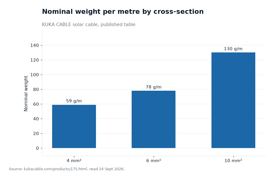
The chart shows the jump rather than the slope. Between 4 mm² and 6 mm² the weight rises by 32%, from 59 to 78 g/m, while the diameter grows only from 5.5 mm to 6.0 mm. Between 6 mm² and 10 mm² the weight rises by 67%, from 78 to 130 g/m, and the diameter by 1.5 mm. Both percentages are my arithmetic on the published figures.
That combination is what breaks a clip schedule copied from the previous project. A slightly wider jaw is needed, and a noticeably shorter span. Buyers who plan the fixings after the solar wire has been ordered usually discover the second point on site, with the reels already delivered.
Comparing clip loads in kilograms
Work one span through. A 750 mm support spacing on a 6 mm² run means each clip holds 0.75 m of cable: 78 g/m × 0.75 m is 58.5 g. Drop the spacing to 400 mm and the load per clip falls to 31.2 g. On 10 mm² the same 400 mm spacing gives 130 g/m × 0.4 m, which is 52 g. These figures are mine, converted from the published nominal weights, and they assume a dry horizontal run with no ice, no wind load and no tension from a bend.
The comparison that matters is between clips, not between projects. A vertical drop of 3 m in 10 mm² puts 390 g on the highest fixing before any dynamic movement, while the same drop in 4 mm² puts 177 g there. Supporting a heavier cable with the same number of fixings shortens the service interval rather than the bill.
Frequently asked questions
Should a clip be ordered by cross-section or by diameter?
By diameter. The cross-section names the conductor, while the clip closes on the finished cable, and the manufacturer publishes outside diameters of 5.5 mm at 4 mm², 6.0 mm at 6 mm² and 7.5 mm at 10 mm² for the same range, so the two figures never move together.
Does the manufacturer publish a clamp spacing figure?
No. The site publishes the nominal weight per metre, the overall diameter, a bending radius of 4 × the outer diameter and a test list that includes cold bending and static flexibility, but it publishes no fixing spacing and no clip recommendation, so spacing stays an installation decision.
What to put on the fixing schedule
Start with the measured diameter of the cable you actually received, not the cross-section on the purchase order. Then record the bend radius you are working to: at 4 × the outer diameter, a 10 mm² cable needs 30 mm of clear curve at every direction change, and a clip placed inside that curve is holding the cable under permanent load. Then note the temperature the installation will see in service, because a range of −40 °C to +90 °C is published for the family and the published bending figure is a cold-bending limit rather than a warm-day suggestion.
Finally, ask for the documents that make the schedule auditable: the datasheet for the exact model, the batch test record covering the spark test at 10 kV and the finished-cable test voltage of 6.5 kV AC for five minutes, and the certificate copy for the model. The manufacturer's own pages carry the range at the solar cable section, the dimensional table at the cross-section page and the laboratory work at the published test list, so every figure above can be checked against its source before a clip is specified.
All weights and diameters in this article on clips and wire come from the manufacturer's own website and were compiled 24 Sept 2026[1].